


Please Leave Us A Message
Privacy statement: Your privacy is very important to Us. Our company promises not to disclose your personal information to any external company with out your explicit permission.

Guangdong Shunde Teamwork Model Technology Co., Ltd
 September 19, 2020
Knowledge sharing by Guangdong Shunde Teamwork Model Technology Co., Ltd, whom with over 20 years rapid prototyping experience. Email: ken@gdtwmx.com Website: www.gdtwmx.com
1 Introduction
Rapid Prototyping technology is a general term for group technology that has been developed in recent years to directly produce prototypes or parts based on CAD models. This technology solves the problem of "visible, intangible" in three-dimensional modeling in computer-aided design (CAD), which can quickly and automatically materialize the geometry on the screen. It integrates modern scientific and technological achievements such as CAD technology, numerical control technology, laser technology and material technology, and is an important part of advanced manufacturing technology. The essence is to use the integral method to manufacture three-dimensional entities, transfer any three-dimensional body information stored in the computer to the molding machine, and directly manufacture them by layer-by-layer addition method without special molds, tools or manual interference.
2 Domestic and international dynamics and development trends
The United States has been at the forefront of developing rapid auto-forming technology, and some well-known universities such as the Massachusetts Institute of Technology, the University of Texas, and a number of research institutions have received significant development and research funding from the government and industry for this technology. Further research. Major companies have purchased molding machines to meet the market demand for race against time. Japan, Germany, and the United Kingdom are all studying new molding technologies and developing new products. More than 2,500 rapid prototyping machines are now available in different areas around the world.
Since the advent of rapid automatic molding, foreign countries have attached great importance to their integration with traditional precision casting technology, which has led to rapid casting. The application of rapid prototyping technology in investment casting can be divided into three types: one is the disappearing molded part (mold) process, which is used for the production of small parts; the other is the direct shell method, which is also used for the production of small parts; It is a fast wax mold manufacturing machine for mass production. Compared with traditional precision casting, these three methods solve the bottleneck problem of the wax mold manufacturing of the traditional method. The flow chart is shown in Fig. 1.
Conventional process rapid prototyping lost foam rapid prototyping ceramic mold

Figure 1 Schematic diagram of the rapid casting process
At present, there are mainly Beijing Longyuan, North China Institute of Technology, Huazhong University of Science and Technology, etc. in the rapid prototyping equipment production and process research. The manufacturers that use the rapid automatic forming technology to produce wax molds for precision casting mainly include the Aviation Materials Research Institute, the Beijing Iron and Steel Research Institute, and the Xi'an Aerospace Engine Factory, which have achieved good economic benefits. At present, this technology has been applied to aviation, aerospace, machinery, chemical, pharmaceutical and other industries.
Our company chose AFS-320MZ equipment produced by Beijing Longyuan Rapid Prototyping Co., Ltd. The equipment adopts solid-state powder material layer-by-layer selective laser sintering technology. At present, it is mainly combined with the company's existing precision casting process to produce wax molds for investment casting.
3 Laser rapid prototyping of wax patterns
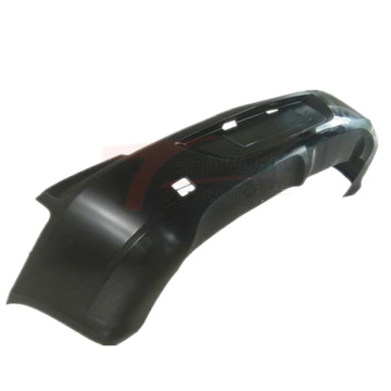
Our company used the traditional precision casting process shown in Figure 1 before introducing rapid prototyping technology. For the development of new products, the production cycle is quite long, and the design and production of the press type takes a long time. As shown in Figure 2, the shape of the bracket is not complicated. If the design is used for production, the design and production cycle of the mold will take about 2 to 3 months. It takes half a month for the mold to be put into production. time. The rapid prototyping equipment just has the advantage in this respect. With its characteristics, the part wax pattern can be obtained within 3 days, and the casting can be obtained in half a month.

Figure 2 bracket parts drawing
The most important thing is to control the size and deformation of the wax mold by using laser rapid prototyping equipment. At the same time, the surface quality of the wax mold should be improved as much as possible.
3.1 Wax size control
Our company now uses Pro_Engineer for 3D modeling and converts it into STL file format; then uses Magics RP software to import the STL file, slice it properly, slice it, and export the CLI format file; then use Longyuan's ARPS software to Convert to the AFI file used by the device; finally import the rapid prototyping device for production.
To control the size of the wax mold, the line shrinkage in the X, Y, and Z directions of the wax mold should be given according to the alloy shrinkage, the mold expansion coefficient, and the process scheme. Once the shrinkage rate is determined, the Magics RP software can be used to first shrink the part, so that the ideal size of the wax pattern can be obtained, and then the casting can be obtained. The size of the wax mold can be reconciled by measuring the size of the casting, and finally the qualified wax mold and casting can be obtained. For example, a steel casting is produced according to the original process plan, and its comprehensive shrinkage rate is set to 2%. After the actual measurement of the casting, the comprehensive shrinkage rate becomes 1.7%, and only under the Magics RP software, the model is The size of the wax pattern can be corrected by scaling and adjusting. If the production is carried out, the adjustment of the shrinkage rate may lead to its scrapping, and in addition to causing a substantial increase in cost, the production cycle is at least half a year late.
In the process of casting production, there are non-free shrinkage conditions such as shrinkage, which leads to serious nonlinear shrinkage of the casting, which in turn affects the dimensional accuracy of the casting. We can consider the three-dimensional modeling when using Pro/Engineer, and draw the actual according to its contraction relationship. The size of the wax mold used will ultimately result in a qualified casting.
3.2 Wax mold deformation control
How to effectively control the deformation of the wax pattern requires understanding the sintering principle of the laser selection. The main structure of the laser sintering forming system of Beijing Longyuan Constituency is: two piston cylinders are installed in one closed molding chamber, one for powder supply and the other for molding. At the beginning of the processing, the powder supply piston is moved up by a certain amount, and the powder roller rolls the powder evenly on the processing plane. Under the control of the computer, the laser beam is scanned through the laser window at a certain speed and energy density, and the laser beam is swept. At the same time, the powder is sintered into a layer of a certain thickness, and the unswept place is still a loose powder, so that the first layer of the part is manufactured. At this time, the forming piston moves down a certain distance, which is the same as the slice thickness of the design part, and the powder supply piston moves up by a certain amount. After the powder roller again flattens the powder, the laser beam begins to scan according to the information on the second layer of the design part. After the laser sweep, the second sheet formed is also sintered on the first layer. Repeatedly, a three-dimensional entity is created. As shown in Figure 3.

Selective laser sintering is different from many other rapid prototyping methods and does not require a stand. The loose powder that was not sintered before laser sintering was made into a natural scaffold. This is effective for the manufacture of parts containing overhangs, hollowed areas, and nothces within notches. These loose powders can be heat-treated to make them adhere. The higher the heating temperature, the higher the degree of squashing, and the more significant the support effect on the parts, the better the deformation of the parts (wax mold) can be prevented; The higher the unsintered powder is, the more difficult it is to clean the wax pattern; therefore, we need to take various measures to prevent the deformation of the wax pattern. Below are examples of several typical parts.
3.2.1 Support
The schematic diagram of the support is shown in Figure 4. As can be seen from the cross-sectional view, the wall thickness of the part is large, and the laser power is 22.5W according to a layer of 0.2mm. The thin-walled and thick-walled intersection of the wax mold produced by sintering has a circle in the circumferential direction, about 10 mm in the direction of the part axis, and about 1.2 mm in the deepest portion in the middle. The reason for this is due to the large difference in wall thickness, the thermal knot, and the uneven sintering of the powder. Therefore, we have hollowed out the three-dimensional prototype of the wax mold, and added some supporting sheets to the hanging boss to prevent deformation, as shown in Figure 5.


It can be seen from Fig. 5 that the three-dimensional prototype wall after hollowing is 4 mm thick. Then, the model is sliced and laser-selected and sintered using the original parameters, and the obtained wax mold has no shrinkage, and the strength can meet the requirements of subsequent work. Moreover, the hollowing and wall thickness homogenization treatment greatly reduces the cross-sectional area of the wax mold, and reduces the sintering time of the laser selective region from the original 8.5 h to the current 4.5 h, shortening the laser sintering time by about half; meanwhile, due to the wax The internal PSB powder in the mold has not been sintered, and a large amount of powder can be saved after the drilling is poured out, and the waxing time can be shortened after the wax mold is hollowed out. In summary, the wax pattern of the part can greatly reduce the raw material cost and the production cost, and the labor intensity of the subsequent work can be reduced due to the weight reduction of the wax mold.
3.2.2 box
The box diagram is shown in Figure 6. The part has a minimum wall thickness of 2 mm and a maximum profile size of more than 400 mm. Considering the problem of easy deformation of thin-walled large planes, the reinforced process is adopted, and the size of the parts exceeds the size of the forming cylinder of the equipment, and only the final combined process scheme of the block sintering is adopted. In order to ensure the maximum dimensional accuracy of the wax mold, the following scheme is adopted.

Figure 6 box schematic
As shown in Figure 7, the four ears of the part are cut to ensure the main structural dimensions, and the dimensions of the parts after the cutting meet the production requirements of the equipment. Then, the thickness of the cut layer was set to 0.15 mm, the laser power was 25 W, and the surface heating temperature of the powder was 95 °C. From the perspective of laser sintering, the selective sintering laser beam is alternately scanned in the X and Y directions. After the rotation of 45°, the length of the laser of the same energy passes through the scanner becomes shorter, and the energy per unit area is increased, which is beneficial to improve sintering. Prototype strength.

Figure 7 process diagram
3.2.3 Multi-pass parts
The schematic diagram of the multi-pass part is shown in Figure 8. The two flanges of the part are required to be very high. The deformation can not be prevented by the reinforcement. Finally, the anti-deformation method is used to artificially increase the angle of the two flanges. After the wax mold is processed, the measurement angle is just within the tolerance range and is suspended. Support the sheet at the flange and the elbow to prevent deformation.

Figure 8 Schematic diagram of the multi-pass part
The above are several typical deformation phenomena, which can be summarized and summarized, we can apply it to other parts, reduce errors and increase the success rate of model sintering.
3.3 Wax mold surface quality control
After the prototype of the wax mold is formed by the rapid prototyping mechanism, the unsintered powder attached to the prototype is first cleaned, then the wax is immersed, and the wax mold is placed in a wax liquid of 65-70 ° C, soaked, and after no bubble overflow, The wax mold was taken out and allowed to stand to precipitate excess wax. After the wax mold is cooled to room temperature, and then finishing treatment, a wax mold having a smooth surface can be obtained.
4 Rapid prototyping wax mold combined with precision casting process
For the precision casting process, the wax mold is used in the subsequent process of wax mold combination, coating, and dewaxing. In order to meet the requirements of the precision casting process, the laser rapid prototyping wax mold must meet its requirements in the above three aspects.
4.1 Module combination
After the laser forming wax is molded, it is necessary to carry out the pouring riser combination according to the process requirements. According to our test, the laser forming wax mold can be repaired, combined and bonded by using the existing medium temperature wax material in the workshop. The bonding strength of the two is sufficient to meet the strength requirements of the shell. Therefore, according to cost, machine addition, and production cycle considerations, the pouring riser generally uses the existing gating system in the workshop. Due to the simple shape of the pouring riser, even if the pouring system of the workshop is not suitable, it is convenient and quick to process the pressing type.
4.2 Module coating shell
After testing, the rapid prototyping wax mold has good coating properties, and can be completely prepared by using the original process, the module is coated with the shell, the surface layer of silica sol + zircon powder coating, the reinforcing layer of ethyl silicate + coal gangue coating.
4.3 Dewaxing
Due to the high melting temperature of the rapid prototyping wax mold, the steam dewaxing process cannot be used. For this purpose, a special process is designed. Firstly, the pouring riser made of the medium temperature wax material in the module is removed by using the existing core baking oven in the workshop. The mold is then placed in a self-made simple tooling, placed in a well-type resistance furnace, baked in an open environment, and the rapid prototyping wax mold is removed. Through the visual inspection after dewaxing, and referring to the surface quality of the cast after casting, it was found that the rapid prototyping wax mold after the demolding (baking) can be basically evaporated, and the residue has no effect on the final casting.
4.4 Form shell roasting, casting, casting cleaning
The shell roasting, casting, casting cleaning and the original casting process are the same.
5 Conclusion
Through the research of laser rapid prototyping technology, the production of single-piece small-volume investment precision castings with tight tasks and time is reduced by 60% compared with the traditional precision casting production cycle, which greatly saves costs. It has been successfully used in a variety of aerospace products.
The combination of rapid automatic forming technology and the existing precision casting process in the foundry allows the foundry to quickly produce various types of wax molds for large-size, complex-structure investment castings, reducing the amount of external costs, while The production of small-volume investment castings can eliminate the need for molds, thus saving a lot of mold processing costs, greatly shortening the production cycle, obtaining a lot of valuable time for the development and development of new products, reducing production costs, and also making the precision casting level in the foundry. The improvement has laid a good foundation for ensuring the smooth completion of precision casting production tasks in subsequent models.
The above is the Process combination application of laser rapid prototyping and traditional precision casting technology we have listed for you. You can submit the following form to obtain more industry information we provide for you.
You can visit our website or contact us, and we will provide the latest consultation and solutions
Send Inquiry
Most Popular
lastest New
Related Products
Send Inquiry

Privacy statement: Your privacy is very important to Us. Our company promises not to disclose your personal information to any external company with out your explicit permission.
Fill in more information so that we can get in touch with you faster
Privacy statement: Your privacy is very important to Us. Our company promises not to disclose your personal information to any external company with out your explicit permission.